


One of the buzzwords used heavily in the IT industry for the past couple of years is the term IoT, which stands for Internet of Things. IoT refers to all of the things that are, well, connected to the Internet, and that's how it got its name. However, IoT isn't really a new concept, because for as long as we can remember, we've been connecting devices to the Internet.
In this article, we'll take a closer look at IoT and what it means to developers. In particular, we'll use the Raspberry Pi as an example, and explore some of the cool things that you can build using it.
The term IoT is so overused that some people in the industry are renaming it to IoE – Internet of Everything, because almost everything is connected to the Internet in some way.
What the Internet of Things (IoT) Really Is
According to Wikipedia, IoT is defined to be:
"...the network of physical objects - devices, vehicles, buildings and other items - embedded with electronics, software, sensors, and network connectivity that enables these objects to collect and exchange data".
Although this is a fairly accurate description of the roles played by IoT systems, it's our opinion that IoT is more than the collection of data-using sensors. More specifically, IoT involves the processing of the data (often Big Data) collected to derive useful information and support better decision-making (see Figure 1). For example, in some countries, rain gauges have been installed to measure the amount of rainfall throughout the year, and the data collected have been analyzed and used to better manage flash floods.
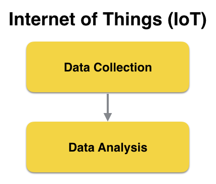
Besides data collection and data analysis, the ability to act on the data collected instantly is also an important criterion in deciding if a system is an IoT system. If the data gathered by rain gauges installed in drains in the previous example indicated that a particular drain has an unusually high level, the maintenance crew is alerted and dispatched immediately to monitor and address the situation.
IoT and the Maker Movement
Another factor driving the momentous adoption of the IoT system is the rise of the maker culture. The maker culture encourages hobbyists (and professionals alike) to create their own devices as well as tinker with existing ones to find solutions to solve their specific problems.
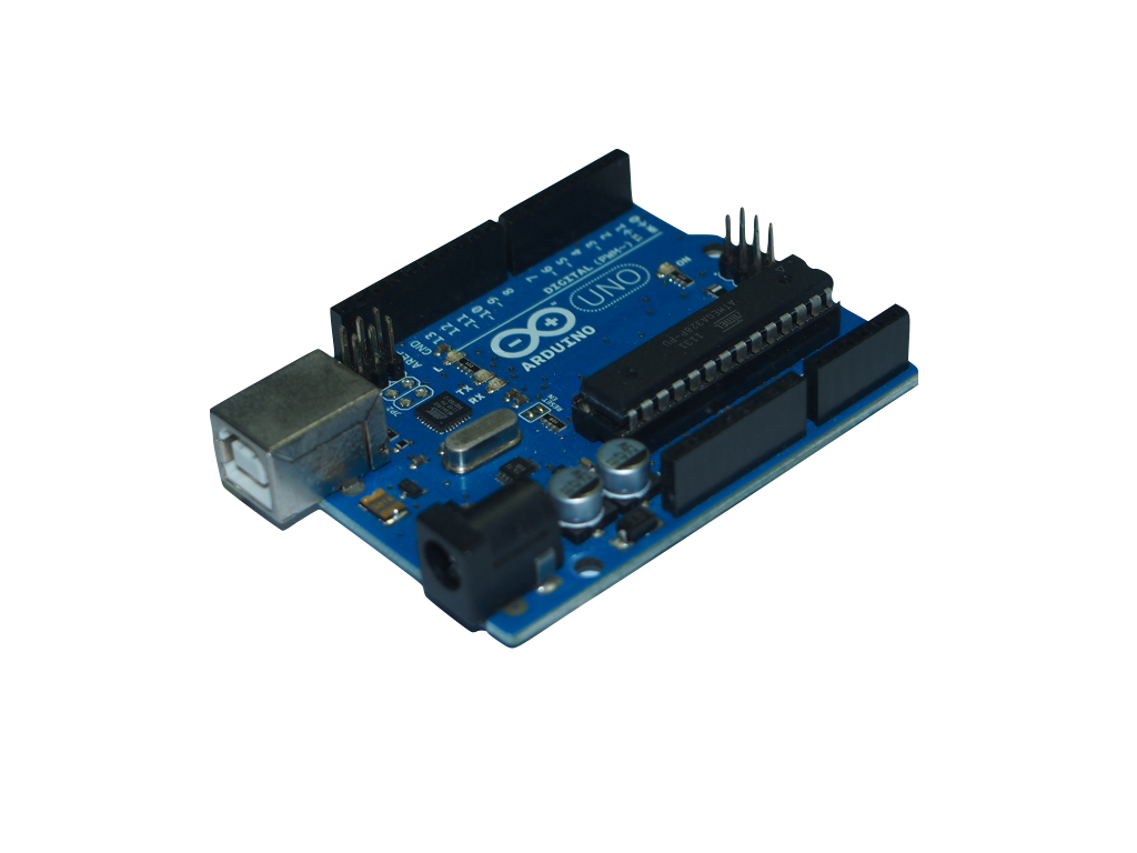
With the maker movement comes a host of DIY electronic platforms, such as Arduino and Raspberry Pi. Arduino (see Figure 2) is a small and inexpensive electronic board that allows you to connect to various external accessories (such as sensors) and create applications to use the data collected.
Another open-source hardware platform that has gotten very popular with hobbyists these days is Raspberry Pi. It's really a computer, by all definitions. Raspberry Pi is a low-cost, credit card-sized computer that connects to a computer monitor or TV using HDMI, and uses a standard keyboard and mouse. It can run a host of operating systems, such as Raspbian (Debian Linux), Android, Windows 10, IoT Core, etc.
Raspberry Pi has gone through a few iterations and Table 1 shows the list of Raspberry models released over the years and their prices.
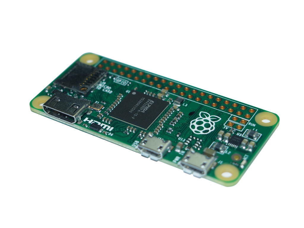
Of the various models, Raspberry Pi 3 (see Figure 3) and Raspberry Pi Zero (see Figure 4) stand out.
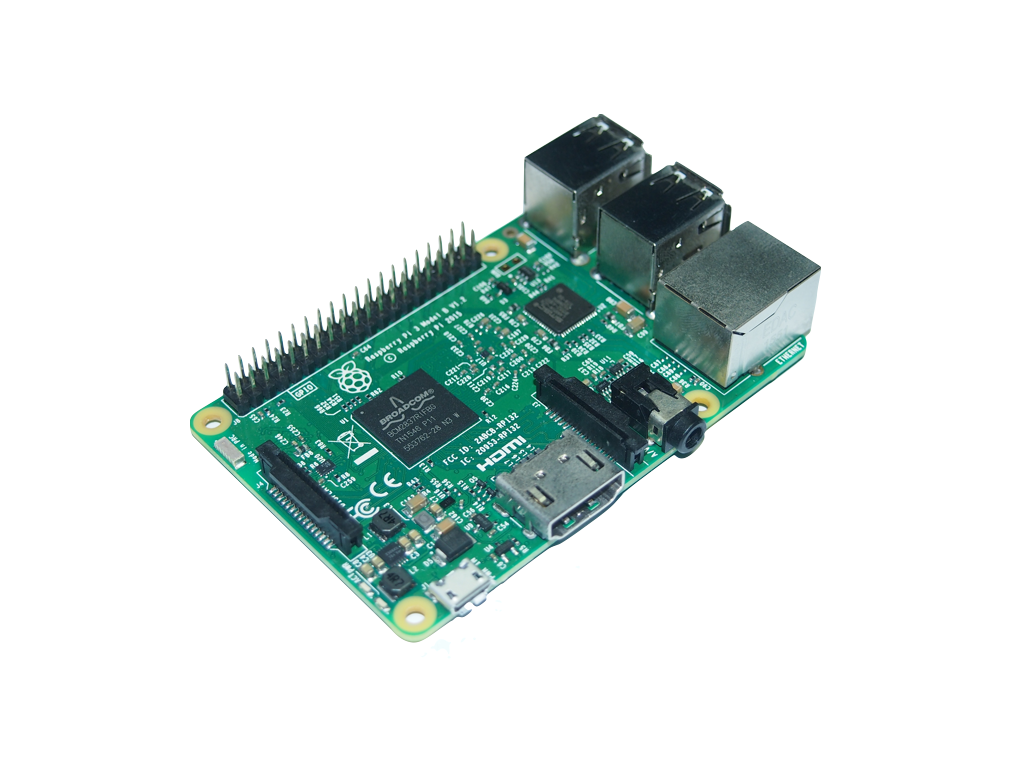
Raspberry Pi 3 is the third generation of Raspberry Pi and it packs quite a formidable punch in its credit card-sized package. Most notably, in addition to the standard features of the Raspberry Pi (such as four USB 2.0 ports and built-in Ethernet), it has:
- A 1.2GHz 64-bit quad-core ARMv8 CPU
- 802.11n Wireless LAN
- Bluetooth 4.1 Low Energy (BLE)
The powerful CPU coupled with Wireless LAN and Bluetooth 4.1 radio makes it an ideal candidate for IoT projects, because multiple sensors can be connected to it simultaneously. In addition, the Raspberry Pi has a 40-pin GPIO (General Purpose I/O) connector for interfacing with external sensors.
The Raspberry Pi Zero is the smallest Raspberry Pi ever made, and although it doesn't have a processor that's as powerful as the Pi 3, its small size is especially suited for embedded projects (such as wearables, etc.), where space is a premium.
Powering the Raspberry Pi
One of the most popular OSs used for the Raspberry Pi is the Raspbian Operating system. The Raspbian OS is based on the Debian OS, optimized for the Raspberry Pi hardware. The easiest way to install the Raspbian OS for the Raspberry Pi is to download NOOBS from https://www.raspberrypi.org/help/noobs-setup/. NOOBS stands for New Out Of Box Software.
The easiest way to install the Raspbian OS for the Raspberry Pi is to download NOOBS from: https://www.raspberrypi.org/help/noobs-setup/.
The Raspbian OS boots off a micro-SD card and the entire operating system runs off the card. A typical Class 4 8GB micro-SD card is sufficient for most purposes, but you have the option to connect it to an external hard disk or flash drive for more storage.
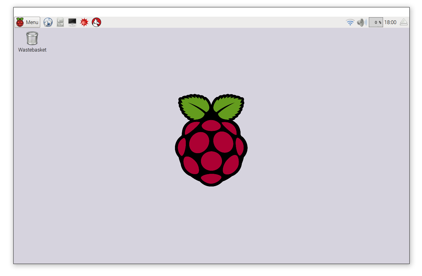
Once the Raspbian OS is installed, you can proceed to log into it and see a full windowed system (see Figure 5). The default username is pi and the password is raspberry.
Connecting the Raspberry Pi to the Outside World - GPIO Pins
The Raspberry Pi has a 40-pin GPIO (General Purpose Input/Output) connection, which makes it very easy to connect to the outside world. To connect the GPIO to external sensors, you can:
- Connect the sensors directly to the GPIO pins using jumper wires
- Connect the GPIO pins to a ribbon cable, which in turn connects it to a breadboard. The Adafruit Pi T-Cobbler Plus - Breakout + Cable for Raspberry Pi A+/B+/Pi 2/Pi 3 (see Figure 6) is one such product. This option is ideal during the prototyping phase.
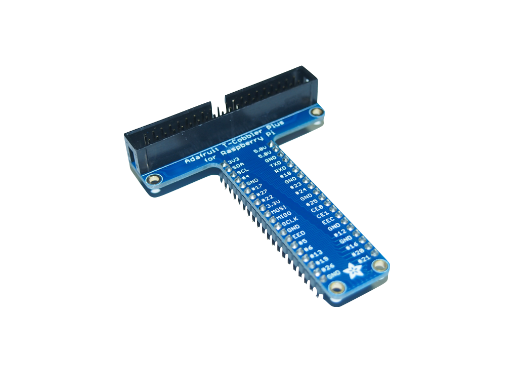
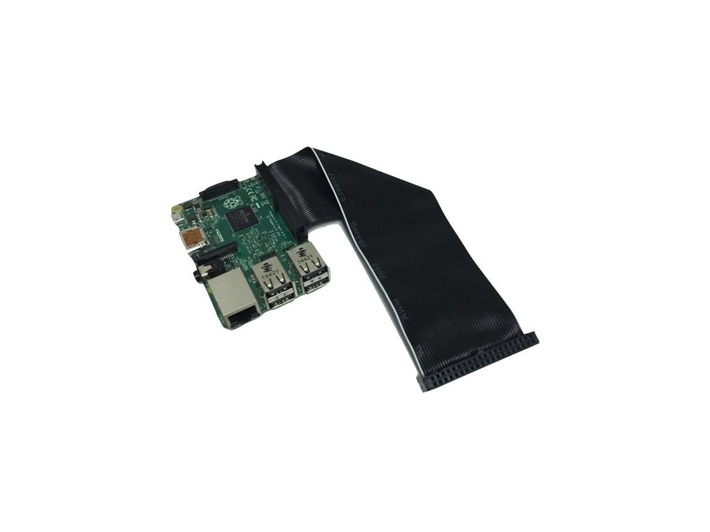
For project prototyping, my favorite is using the second option: the Adafruit Pi T-Cobbler Plus. The Adafruit Pi T-Cobbler Plus connects to the Raspberry Pi via a ribbon cable (see Figure 7).
Examining the GPIO Pins
One of the advantages of using the Adafruit Pi T-Cobbler Plus is that you have a clear labeling of the various GPIO pins (see Figure 8).
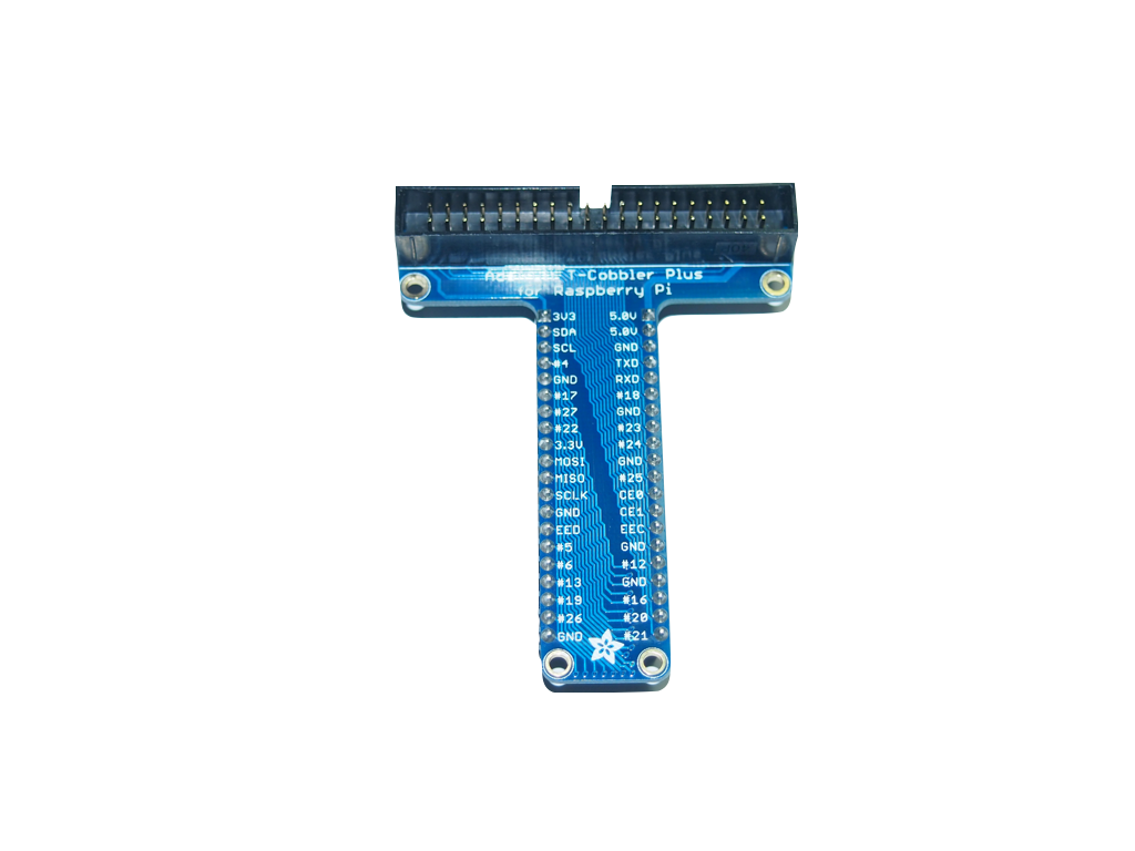
The GPIO pins on the Raspberry Pi are divided into the following groups:
- Power: Pins that are labeled 5.0v supply 5 volts of power and those labeled 3V3 supply 3.3 volts of power. There are two 5V pins and two 3V3 pins.
- GND: These are the ground pins. There are eight ground pins.
- Input/Output pins: These are the pins labeled with the # sign, for example, #17, #27, #22, etc. These pins can be used for input or output.
- I2C: I2C is a serial protocol for a two-wire interface to connect low-speed devices like microcontrollers, EEPROMs, A/D and D/A converters, I/O interfaces, and other similar peripherals in embedded systems. These pins are labeled SDA and SCL.
- UART: The Universal Asynchronous Receiver/Transmitter allows your Raspberry Pi to be connected to serial peripherals. The UART pins are labeled TXD and RXD.
- SPI: The Serial Peripheral Interface is a synchronous serial communication interface specification used for short distance communication, primarily in embedded systems. The SPI pins are labeled MOSI, MISO, SCLK, CE0, and CE1.
- ID EEPROM: Electrically Erasable Programmable Read-Only Memory is a user-modifiable read-only memory that can be erased and written to repeatedly through the application of higher than normal electrical voltage. The two EEPROM pins on the Raspberry Pi (EED and EEC) are also secondary I2C ports that primarily facilitate the identification of Pi Plates (e.g., Raspberry Pi Shields/Add-On Boards) that are directly attached to the Raspberry Pi.
Connecting to a Sensor to Detect Motion
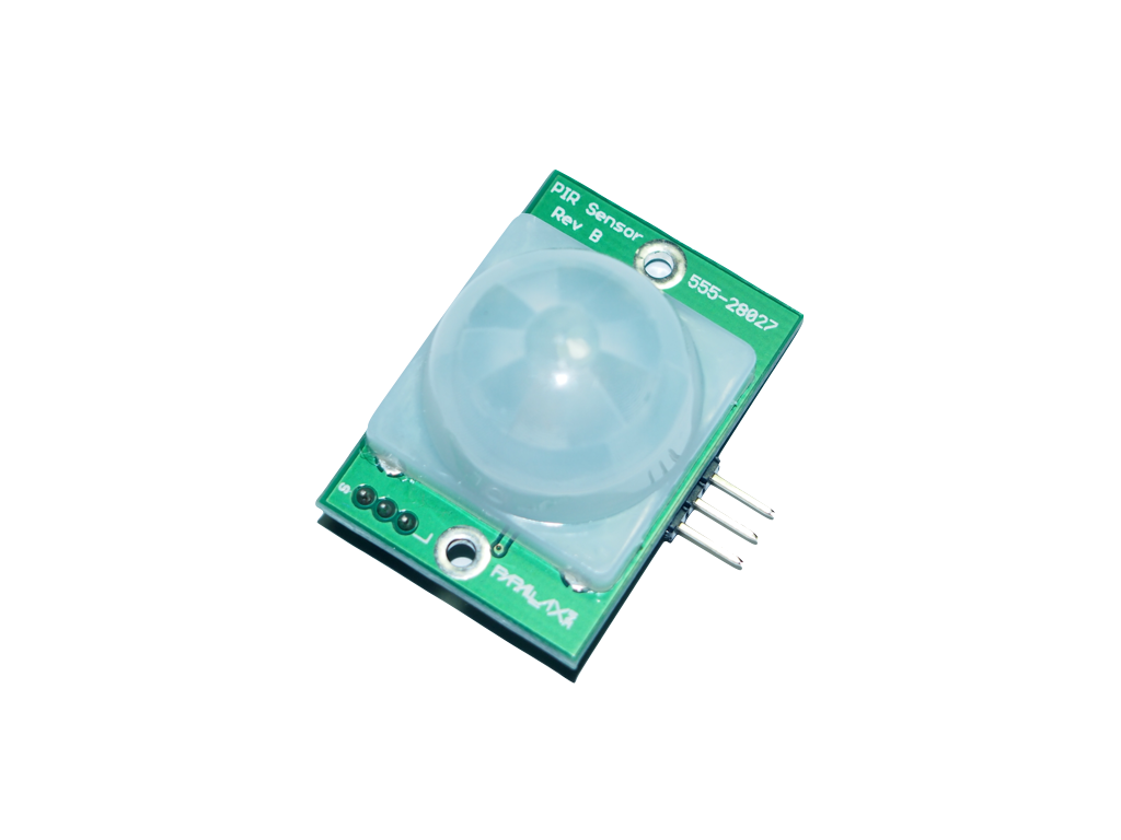
To demonstrate how to use the GPIO to connect to an external sensor, we'll now use a PIR motion sensor to detect motion. For this, I used the Parallax PIR Motion Sensor (see Figure 9). The PIR Sensor detects motion by measuring changes in the infrared (heat) levels emitted by surrounding objects of up to three meters.
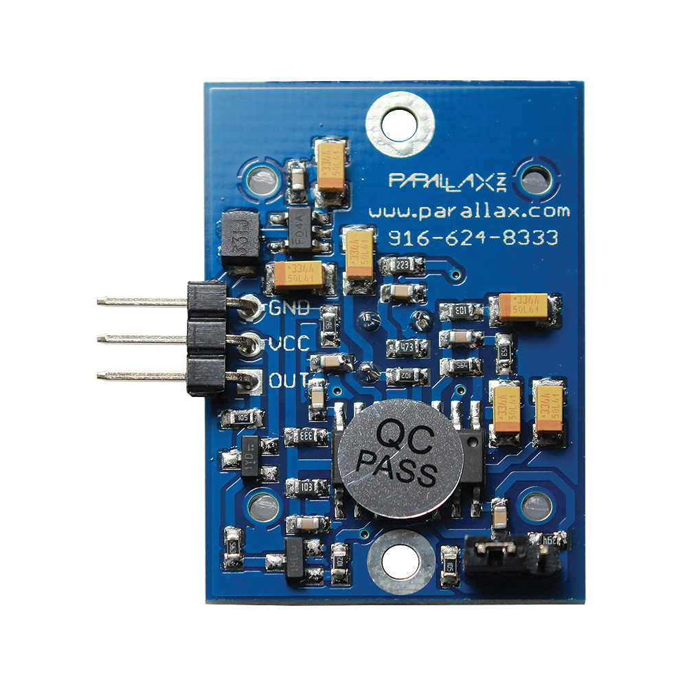
The Parallax Motion sensor has three pins (see Figure 10):
- GND: The ground pin. Connect this pin to the GND on the GPIO.
- VCC: The voltage pin. Connect this pin to one of the 5V pins on the GPIO.
- OUT: The output pin. Connect this to one of the Input/Output pins on the GPIO.
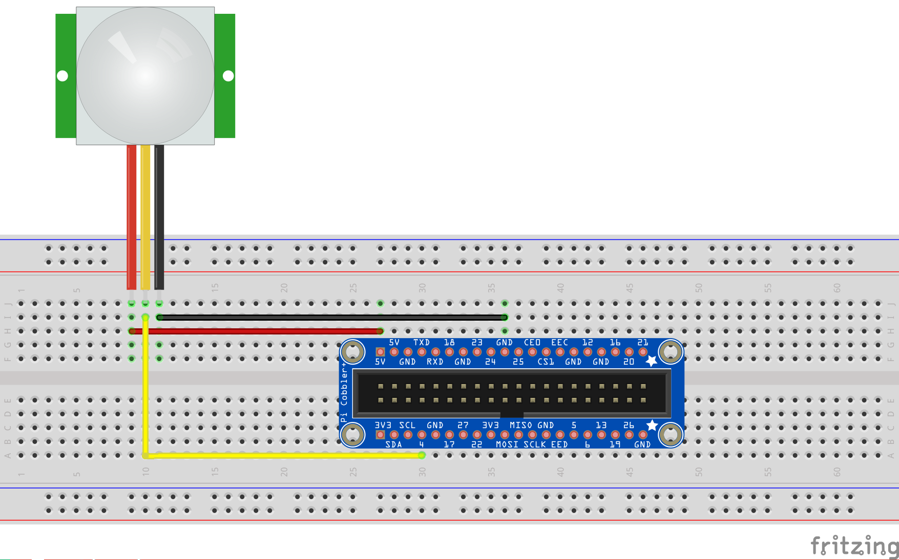
When the PIR Motion sensor detects motion, it outputs a high signal on its output pin. You need to write an application to read the value of this output pin. Figure 11 shows a PIR Motion sensor connected to the T-Cobbler Plus.
Depending on the PIR Motion Sensor that you're using, the arrangement of the various pins isn't always in the same order as described. It's important to verify and connect the correct pins to the correct GPIO pins. Connecting the wrong pins to the Raspberry Pi can permanently damage the PIR Motion Sensor.
In the figure, the red line is the VCC and should be connected to the 5V pin on the GPIO. The yellow line is the OUTPUT and is connected to pin #4 on the GPIO. The black line is the GND and should be connected to GND on the GPIO.
Bonding the Raspberry Pi and the Sensors: The Python Programming Language
Now that the Raspberry Pi is connected to the PIR Motion Sensor, it's time to write the code to make things work. In the Raspbian OS, Python is a first-class citizen, and the support for Python comes right out of the box. With its clean syntax and ease of learning, Python is a first choice for hobbyists and beginners to foray into the world of the Raspberry Pi. Coupled with the huge community support for Python, it's no wonder that it's the language of choice for developers.
Open a Terminal window in the Raspbian OS and create a text file by typing the following command:
$ nano motiondetection.py
The above command uses the NANO text editor and creates a file named motiondetection.py. Enter the statements as shown in Listing 1.
Listing 1. Source code for using a PIR Motion Sensor
import RPi.GPIO as GPIO                        #1
import time                                    #2

pirsensor = 4                                  #3
GPIO.setmode(GPIO.BCM)                         #4
GPIO.setup(pirsensor, GPIO.IN, GPIO.PUD_DOWN)  #5

previous_state = False                         #6
current_state = False

while True:                                    #7
    time.sleep(0.1)                            #8
    previous_state = current_state             #9
    current_state = GPIO.input(pirsensor)      #10
    if current_state != previous_state:        #11
        if current_state:                      #12
            print("Motion Detected!")          #13
When you are finished typing in the code, exit the NANO editor by pressing Ctrl-X and then pressing Y to save the file. Press Enter to save it to the current directory. To run the Python script, type the following command in Terminal:
$ python motiondetection.py
Wave your hand in front of the PIR Motion Sensor. You should see the following output on Terminal:
Motion Detected!
Dissecting the Code
Now that you've written your first Python code, it's useful to understand what it does and how it works. We'll dissect the code line-by-line:
The RPI.GPIO is a library that allows your Python application to easily access the GPIO pins on your Raspberry Pi.
- #1: The latest version of Raspbian includes the RPI.GPIO Python library pre-installed, so you can simply import that into your Python code. The RPI.GPIO library allows your Python application to easily access the GPIO pins on your Raspberry Pi. The
askeyword in Python allows you to refer to the RPI.GPIO library using the shorter name of GPIO. - #2: The application is going to insert some delays in the execution, so you need to import the time module.
- #3: You declare a variable named
pirsensorto indicate the pin number for which the Output pin on the PIR sensor is connected to the GPIO pin. In this example, it's GPIO pin #4. - #4: There are two ways to refer to the pins on the GPIO: either by physical pin numbers (starting from pin 1 to 40 on the Raspberry Pi 2/3), or Broadcom GPIO numbers (BCM). Using BCM is very useful with a ribbon cable (such as the Adafruit T-Cobbler Plus) to connect the Raspberry Pi to the breadboard. The BCM numbers refer to the labels printed on the T-Cobbler Plus (see Figure 8). For this example, we're using the BCM numbering scheme. That means that when we say we're getting the input from pin 4, we're referring to the pin printed as #4 on the T-Cobbler Plus.
- #5: Initialize the pin represented by the variable
pinsensoras an input pin. Also, we use a pull-down resistor (GPIO.PUD_DOWN) for this pin. - #6: There are two variables to keep track of the state of the sensor.
- #7: We use an infinite loop to check the state of the sensor repeatedly.
- #8: Inserts a slight delay of 0.1 second to the execution of the program
- #9: Save the current state of the sensor.
- #10: The
GPIO.input()function reads the value of the GPIO pin (#4 in this case). When motion is detected, it returns a value oftrue. - #11: Compare the previous state and the current state to see if the motion sensor has a change in state. If there's a change, it means that either the sensor has just detected motion (when the state changes from
falsetotrue), or that the sensor is resetting itself (when the state changes fromtruetofalse) a few seconds after motion has been detected. - #12: If the current state is
true, it means that motion has been detected. - #13: Print out the string “Motion Detected!”
When the PIR Motion Sensor detects motion, its output will be 1 (
true), and a few seconds later, it's automatically reset to 0 (false).
Acting on the Sensor Data
Now that the PIR Motion sensor is sensing motion, let's put it to good use. A good application of this project is to install the Raspberry Pi and the motion sensor at home to monitor for unexpected movement. You could mount the sensor near your door to detect movement outside the house when there's no one at home.
Once motion is detected, the Raspberry Pi could send a push notification to an Android device via the Google Cloud Messaging (GCM). A detailed description of Android and GCM is beyond the scope of this article, but here's what's required for an Android app to receive a push notification:
- The developer of the Android application needs to apply for an API key at https://console.developers.google.com.
- Once the Android application is installed on the device, it needs to register with Google programmatically to obtain a registration ID. This registration ID uniquely identifies the application on a particular device so that GCM can push a message to it.
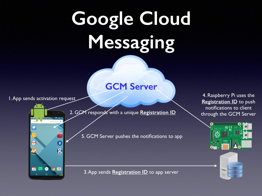
Figure 12 summarizes the interaction between the various parties in a push notification system. In particular, it shows how you can use the Raspberry Pi to send push notifications:
- The Android app sends an activation request to Google's GCM Server.
- When the registration is successful, the GCM Server returns a Registration ID to the app.
- In the real world, the Registration ID should be sent to a server maintained by the developer, who will then save it into a database.
- The developer also needs to write another application to communicate with the GCM server to send the push notification to a particular user(s). In this project, we'll use the Raspberry Pi to send the message to a user via the GCM Server.
- Once the GCM server receives the message, it sends the push notification to the app.
To send a push message via Google's GCM server, you can use a variety of programming languages, such as C#, Python, Node.js, etc. Because Python is already supported in Raspbian, it's natural to use it.
Open a Terminal window in the Raspbian OS and create a text file by typing the following command:
$ nano pushgcm.py
Enter the statements as shown in Listing 2. Be sure to replace the <API_KEY> with that of your own and the <Registration_ID> with that of the registration ID of the Android app installed on a device.
Listing 2. Sending a Push Notification Message using Google Cloud Messaging (GCM)
import requests                                                 #1
import json                                                     #2

gcm_url = "https://android.googleapis.com/gcm/send";             #3

api_key = "<API_KEY>"                                           #4

#replace <reg_id> with your own
reg_id = ["<Registration_ID>"]                                  #5

headers = {'content-type':'application/json',                   #6
           'authorization':'key=' + api_key}

#notification payload
data = {                                                        #7
    "sender" : "Raspberry Pi",
    "event"  : "Motion Detected!"
}

#create a dictionary to store the data to post
post_data = {}                                                  #8
post_data['data'] = data                                        #9
post_data['registration_ids'] = reg_id                          #10

#convert dictionary to JSON
post_data_json = json.dumps(post_data)                          #11
print
print "Data to post to GCM Server"
print "--------------------------"
print post_data_json
print "--------------------------"
print

#post the data to GCM Server
r = requests.post(gcm_url, data=post_data_json,                 #12
                  headers=headers)
print "Response from GCM Server"
print "------------------------"
print "Header : ", r.headers['content-type']                    #13
print "Status : ", r.status_code
print "Text   : ", r.text
print "--------------------------"
Dissecting the Code
As usual, it's useful to understand what the code is doing:
- #1: Import the Requests Python library that helps you to send HTTP requests to a server easily without worrying about query strings, form-encoding your POST data, etc.
- #2: Import the JSON library so that you can print out the data that was sent to the GCM server in JSON format.
- #3: The end point for Google's GCM server.
- #4: The API Key that you've obtained from Google. This identifies the application developer sending the push notification.
- #5: The Registration ID(s) of the application receiving the notification. You get this Registration ID from the application after it has registered with Google. In the real world, this Registration ID should be sent to the server maintained by the developer to provide a complete list of Registration IDs of the app installed on the users' devices. If you want to send a push message to multiple recipients, separate the Registration IDs with commas (,).
- #6: The HTTP header to sent to the GCM server to authenticate the identity of the sender.
- #7: The content of the push message. Here, you're sending two key/value pairs, indicating who's sending the message and the event. For GCM push messages, you can send multiple key/value pairs. The Android application receiving the push message simply specifies the key(s) to extract the value(s).
- #8: You create a dictionary to store the content of the push message together with the registration ID(s) of the recipient(s).
- #9: You set the content of the push message in the dictionary.
- #10: You set the recipient(s) of the push message.
- #11: You use the
json.dumps()function to convert thedictionaryobject into a JSON string so that you can print it out to examine its content. - #12: You use the
requests.post()function to post the push message to the GCM server. - #13: After the message was sent to the GCM server, it responds with the status. Here, you print out the content type of the response, followed by the status of the HTTP request, as well as the details of the sending (such as if the message was successfully sent or failed to send, the ID of the message, etc.).
Before you can run the Python code to send a push notification to the Android device, you need to download and install the Requests Python library. To do that, type the following command in Terminal:
$ sudo pip install requests
Once Requests is installed, type the following command to execute the pushgcm.py script:
$ sudo python pushgcm.py
If the push message is delivered successfully to the GCM server, you should create an output similar to the following:
Data to post to GCM Server
--------------------------
{
    "registration_ids": ["<Registration_ID>"],
    "data": {
        "event": "Motion Detected!",
        "sender": "Raspberry Pi"
    }
}
--------------------------
Response from GCM Server
------------------------
Header :  application/json; charset=UTF-8
Status :  200
Text   :  {
    "multicast_id":8838766867169688347,
    "success":1,
    "failure":0,
    "canonical_ids":0,
    "results": [
        {
            "message_id":"0:1461392749167691%62851a86f9fd7ecd"
        }
    ]
}
--------------------------
To complete this project, you need to modify the motiondetection.py script so that when a motion is detected, the pushgcm.py script is called to send a push notification to the Android application. Listing 3 shows the addition.
Listing 3. Calling the pushgcm.py from motiondetection.py
import RPi.GPIO as GPIO
import time
import os                                      #1
pirsensor = 4

GPIO.setmode(GPIO.BCM)
GPIO.setup(pirsensor, GPIO.IN, GPIO.PUD_DOWN)

previous_state = False
current_state = False

while True:
    time.sleep(0.1)
    previous_state = current_state
    current_state = GPIO.input(pirsensor)
    if current_state != previous_state:
        if current_state:
            print("Motion Detected!")
os.system("python pushgcm.py")       #2
In line #1, you need to import the os module so that when motion is detected you can use the os.system() function (in line #2) to perform a shell operation - specifically, to execute the pushgcm.py script.
Summary
In this article, we've attempted to define what an IoT system is and to illustrate it with a very simple and practical example: using the Raspberry Pi and detect motion and triggering a push notification when one is detected. We welcome your comments and ideas on the IoT systems that you've built.
Table 1: The Raspberry models released over the years
| Models | Price |
| Raspberry P1 Model A | US $25 |
| Raspberry P1 Model A+ | US $20 |
| Raspberry P1 Model B | US $35 |
| Raspberry P1 Model B+ | US $25 |
| Raspberry P2 Model B | US $35 |
| Raspberry P3 Model B | US $35 |
| Raspberry P1 Zero | US $5 |